by Russ O’Brien
Purpose:
To stop oil leakage at the forward end of the crankshaft and improve lubrication of the timing chain.
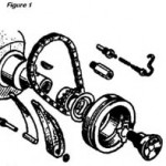
Background:
The evolution of oil seals has progressed from no seals at all to modem elastomeric lip seals, which stop oil leakage for very long service periods. In between these extremes, attempts have been made using leather, rope, cork, felt, canvas, string, rags, etc. Most set-ups had a short useful lifetime or had a mechanism of springs or threaded nuts which required periodic tightening. The most effective leak-stoppers were cumbersome an extracted considerable power due to friction drag. The labyrinth and disc slinger system, used in the Alpine, does a partial seal job. With its reverse thread and no parts wearing, it does not change with time, but it steadily leaks.
The four-cylinder Sunbeam Alpine engine was designed with a labyrinth seal (Rootes PT # 1228021 Damper Ring) and a slinger disc (Fig. 1) at the forward end of the crankshaft to minimize oil leakage. Since a labyrinth seal is not a leak proof seal, a minimum of oil is pumped to the adjacent timing chain to keep leakage to a tolerable level. Consequently, the drive sprocket wears and the timing chain “stretches” via wear at every link and pin, resulting in retarded valve timing, jumpy valve and ignition timing, and chain slap after the chain has lengthened beyond the range of the tensioner.
Numerous manufacturers have supplied replaceable oil seals for many years. Seals last about 60,000 to 80,000 miles before they leak. The oil seal maintains a light squeeze on the rotating shaft, similar to the squeeze of a stretch watchband on a wrist. Since these oil seals do such a thoroughly good job on other engines, there was a natural urge to adapt one to a Sunbeam and enjoy the benefits.
Adapter, Oil Seal to Timing Chain Cover

A means of mounting an oil seal was needed so that it would be centered on the shaft. After locating the smallest OD oil seal (C/R #1723 1) which would fit over a 1-3/4″ diameter shaft, an adapter was designed for the seal to be pressed into and mounted in the timing chain cover. The adapter was made compact to clear the nearby pedestal bolt inside the timing chain cover. A flange was provided to facilitate high temperature soldering and maintain alignment with the cover (Fig. 2).
Harmonic Balancer Modification

The set maintains contact with the rotating harmonic balancer. As supplied, this surface has a reverse thread labyrinth seal (Fig. 3). The surface is very rough and must be changed to a smooth finish to function with a synthetic rubber lip seal. Welded or brazing fill metal was considered but was discounted. To machine away the reverse thread to a smooth surface would have left the wall too thin at the keyway.
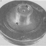
It was decided to machine the reverse thread zone down a little and press on a steel ring with a 0.002″ interference fit (Fig. 4). This tight fit eliminated the need for brazing the parts together. The harmonic balancer was then machined to be concentric with the bore.
Preparing the Timing Chain Cover
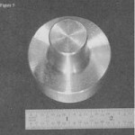
An alignment plug was made to facilitate lining up the cover with the spindle of a milling machine (Fig. 5).

An adjustable fly cutter was used to bore a 2-3/8″ diameter hole to fit the seal adapter (Fig. 6).
Soldering the Adapter to the Timing Chain Cover
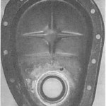
Eutectic #157 high strength, silver bearing solder was used to solder the Adapter to the Cover (Fig. 7). The cover was sand blasted to remove paint before soldering. NOTE: Eutectic #157 solder is four times as strong as ordinary solder, has a melting point of 420 degrees F and stays bright and shiny.
Oil Feed Line to Timing Chain Capillary Tube
A capillary tube, 1/8″ OD, is connected to the pressurized oil gallery and supplies oil to lubricate the timing chain. The capillary tube extends out over the timing chain drive sprocket, and then makes a U-turn back to the sump. Adjacent to the sprocket, a tiny hole is drilled in the side of the capillary to lubricate the chain. The remainder of the oil is squirted back into the sump. With an oil seal in place and with no fear of leakage, all the oil coming through the capillary tube can be directed on the chain and sprocket to gain the maximum benefit of the seal. To do this, cut off the capillary tube as shown in Fig. 1 and point it toward the small drive sprocket. Advantages of this step are improved lubrication of the timing chain and sprocket, less wear and noise from contact with the chain tensioner, and improved oil cooling.

Installation Tips
1. Per an obscure note in the Alpine shop manual, sealing compound should be applied to the left and right sides of the front main bearing cap to prevent oil leakage in troublesome cases (when machining tolerances combine to leave a big gap).
2. A ball and spring check valve is located inside the capillary tube fitting to prevent draining the oil gallery when the engine is off (Fig. 1). This also is in series with the timing chain lubrication system and must not be plugged with sludge.
3. After the Harmonic Balancer has been installed and before the tab washer and nut are installed, sealing compound should be applied around the crankshaft periphery and in the keyway to stop oil leakage.
Conclusion
This modification was a challenge, which involved numerous process steps. However, it was easy once an oil seal was located in standard stock.
Editors note: If you want to avoid expensive machine shop work on the cover, the alignment tool, the seal ring, and the harmonic balance then follow Ed Esslinger’s method that he described in the March 1997 Rootes Review.
I found that a balancer seal from a small block Chevy is a near perfect fit to the Alpine and a balancer repair kit with a sleeve will work. If I cut out the seal mounting area of an aftermarket dress-up timing cover for a small block Chevy I could mount it in the Alpine timing cover and avoid machining. This is is how I did it.
- Using a saber saw with a fine hacksaw blade, cut out the seal mounting area from the cover. Leave as much of the flat area around it as possible.
- Place the balancer on your workbench, hub side up.
- Place the Alpine timing cover over the balancer in its normal operating position (see drawing).
- Place a block of wood under the cover to make it level and stable on the workbench.
- Place the sleeve from the kit over the hub of the balancer.
- Install the new oil seal 1/2 way in the cutout oil seal mount (1/2 way as we need to remove it later).
- Place the mount with the seal over the sleeve inside the timing cover with the bulge side down.
- Locate the notch or file the mount area where the center bolt attaches. Take off no more than necessary to clear mounting stud.
- Place 1/2″ wood spacers under the mounting flange (bulge side down) on two sides.
- Drill a 1/8″ hole through the mount flange, spacer and timing cover on two sides. (This locates the seal center, so drill as vertical as possible. Use a drill press if possible).
- Remove the seal mount, seal,
spacers, sleeve and balancer from the timing cover. - Lay the timing cover inside down on
your work bench and carefully cut out the flat part of the bulged area all the way around. - Place the seal mount inside the cover, bulge side toward front. Make sure your alignment holes line up and the mounting flange is flat against the timing cover.
- Remove the seal mount. Clean the mount area in the timing cover very clean with sandpaper and then wash the area with paint thinner.
- Using a good flux, solid 60/40 solder and a propane torch, tin the cleaned area. Do not fill the 1/8″ alignment holes.
- Remove the seal and sand off the chrome plating down to base metal on both sides of the flange of the seal mount. Clean it with paint thinner.
- Apply flux to the flange of the seal mount, bulge side.
- Mount the seal mount in the timing cover (bulge side out) and secure it with two steel pop rivets in the alignment holes.
- Apply flux to the engine side edge and flow solder all around the mounting area and over the rivets.
- Remove all flux residue with paint thinner.
- Coat the outside edge of the oil seal with liquid Permatex and press it fully into the timing cover, open side toward motor.
- Install the cover on the motor with a new gasket. Do not tighten bolts.
- Clean the balancer hub with sandpaper. Remove all traces of oil and dirt with paint thinner.
- Mix a small amount of J.B. Weld and apply evenly over the entire hub area.
- Rough the inside of the sleeve lightly with sandpaper, clean it and place it over the hub. Press it down as far as it will go.
- Remove the excess J.B. Weld and let set the recommended time.
- Lightly coat the sleeve with wheel bearing grease and install balancer on motor.
- Tighten the timing cover bolts.
Available sleeve part numbers are, Fel Pro 16202 or McCord 82-2004. The cost is about $8.00.
Available seal part numbers are, National 9845, C/R 17286 or Victor 49328. The cost is about $3.00.
The Chevy aftermarket small block chrome timing cover cost is about $ 10.00.

Comments (5)
I am interested in the oil seal to timing chain cover mod for my sunbeam alpine. Can you tell me where I can I get the CR 1723 oil seal, or better still, does anyone sell the complete cover and pully modification?
Hi,
Has anyone fitted the attached timing chain cover, and if so how does it perform?
http://www.joesrestorationrescue.com/?
Kind regards
Lee
Hi I need the up to date oil seal in the front timming cover
What sort of materials will work for sealants? It seems that synthetic rubber is the way to go, but I wonder if there are other things like plastic that would work. I imagine that these seals are very important so that there is no mechanical stripping.
Sam, Sealant types vary for application, of course. In automotive applications there are fillers (seams and gaps), heat transfer, high heat (over 400F), Shellacs for precision metal mating surfaces, etc. Only products resistant to oil should be used in engine applications. That leaves out most popular RTV types, despite what is advertised. The reason is that application of the RTV’s leaves residuals in the interior of an engine. The residuals eventually swell, degrade and break down, crystallize into sand like particles and eventually take the engine or other machine down with it. I witnessed a private plane crash land on my property several years ago for exactly this reason.
There are many products that work well.The biggest cause of sealer failure, aside from inappropriate sealer type, is application preparation. When instructions state clean surface, they usually don’t say how clean. I use this phrase: “If you wouldn’t eat off it, it is not clean enough”. Gasket type surfaces must be oil residue free. PERIOD. brake cleaner, engine degreasers, parts cleaners, etc. leave residues. A more effective approach is to rinse with fresh toluene, acetone or what I like is an aerosol can of carb cleaner to flush surface.
This does not directly answer your question. It is presented to illustrate the various application types and processing that need understood before talking polymers and synthetic rubbers. There is a reason for everything.
Tiger Tom