
originally published as “Alternator Conversions for (with) Dummies OR How I Finally Trained the Smoke in the Prince of Darkness’s Wire Harness” by Ron Fraser in the July 2003 RootesReview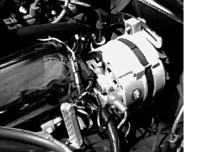
Have you always wanted to convert to an alternator electrical system in your Tiger, but were just a bit too intimidated by it all? Me too, until I had a revelation and the smoke cleared. The approach I’m going to describe will work with any one-wire alternator. For this article, I used an older 1966 Mustang type alternator, which requires an external voltage regulator. I purchased a one-wire regulator conversion kit from AMK that mounts to the back of the Ford alternator. Newer, one-wire alternators do not need this kit.
The Revelation?
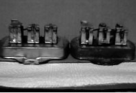
Make a “Dummy Voltage Regulator” that appears factory original but is just a wire junction box to attach the wire harness. Here is all you need to do:
- Open the voltage regulator and remove the 2 sets of points.
- Remove the 3 contact springs.
- Remove the 2 resistors on the bottom.
- Now check for continuity between “A” and “B” posts
- Check to make sure that the “F” post is isolated from the other posts and that all 3 posts are isolated from ground

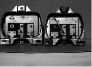
Congratulations you now have a “Dummy Voltage Regulator” that still appears factory original.
Mounting the Alternator
The biggest problem as I see it with this conversion is the alternator bracket. There are several choices. Buy a MK II bracket from one of the vendors, buy a reproduction bracket from Doug Jennings, or make your own bracket. I chose to make my own under-slung bracket. By under-slung, I mean that the alternator mounts over the bracket instead of hanging from the bracket like the MK II style.
The design started at the two cylinder head mounting-bolt holes and the alternator pivot point. I transferred the drawings to plywood and mounted the plywood bracket to the engine. Plywood makes a very cost effective and easy way to check your design. In the first iteration, the pivot point was way wrong. The 2nd iteration put the pivot point too low leaving no clearance for the brake line four-way connector. Finally I got everything right including a rough plywood adjustment arm. Here are the dimensions of the final details. These dimensions are good for the Autolite Alternator I used. Your alternator may be different, so adjust any numbers as needed. Be ready to remove extra material to gain clearance for the alternator and its adjustment swing.
Note: The alternator pulley alignment to the engine pulley is the most critical measurement of this design and must be carefully checked at each step. Different alternators may have a different pulley spacing.
Parts for the Alternator Bracket
I transferred the final drawings to two pieces of 1/8” steel and two pieces of 3/16” steel. I then cut them out and welded the parts together, making a very sturdy mount. After I cleaned up the welds and applied some paint, the bracket was ready.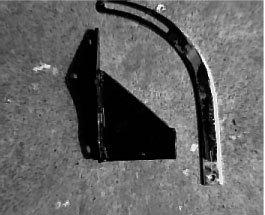
The adjustment bar, shown here, turned out to be easy. I purchased a Mr. Gasket universal adjustment bar # 9851, cut it back 2.6”, drilled a new mount hole and opened up the adjuster slot for a 3/8” bolt. I’m sure Ford or someone made an adjustment arm that would work I just did not have one.
Completed Alternator Bracket and Adjustment Bar
Here are the steps to mount the Alternator to the engine.
- You must adjust the dipstick tube by re-curving the tube. Slow, gentle hand pressure worked just fine.
- Mount the bracket and the dipstick tube with two 3/8” bolts.
- Mount the alternator with a 5” long bolt. A 3/4” thick spacer was also needed here.
- Use a new fan belt, Dayco # 15475
To be absolutely safe, put a big piece of clay on the high point of the alternator and close the hood carefully and check the clearance.
Wiring the New Alternator
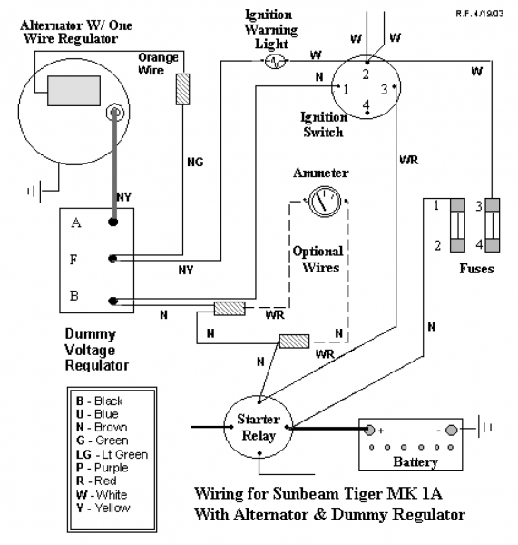
The following instructions are for the Ford Autolite Alternator with an added one-wire regulator. Wiring the new Alternator is quite simple since all the original wires in the harnesses are used. See the wiring schematic below.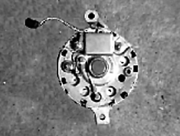
- Attach the one wire conversion kit to the older 1966 Mustang type alternator per kit instructions.
- Attach the heavy-duty brown / yellow (NY) wire to positive post of alternator.
- Attach a black (B) wire to ground post of alternator.
- Attach the brown / green (NG) wire to the orange wire from the one wire regulator. The regulator has an orange wire which connects to the ignition warning light That connection is now made by attaching the brown / green (NG) and the light-duty brown / yellow (NY) ignition warning light wire at the “F” post.
Note: The ignition warning light wire is the only wire that moves in this conversion, it moves from the “A” post to the “F” post.
Caution: The amperage range of the ammeter should match the output of the alternator used in the installation to avoid possible damage the gauge. Although I did not change my 30-amp ammeter, I have had no problems to date.
Parts List
- Ford alternator, 55 amp, from Mustangs Unlimited
- 1 wire voltage regulator from AMK Products Inc.
- Alternator mounting bolts
(1) 7/16” x 5” bolt, nut, washer, and lock washer,
(1) 3/8” x 2” bolt, washer and lock washer
- 3/4” long spacer with 7/16” ID
- Stock voltage regulator (to be modified)
- Mr. Gasket Universal Adjustment Arm # 9851
- Dayco fan belt # 15475 (for the stock alternator pulley)
- 1/8” and 3/16” steel sheet stock to make bracket
This is a template of the mechanical parts. Don’t forget the alignment of the fan belt.
Very important!
 This is the wiring schematic for rewiring of new alternator and the “dummy” regulator which will get you past the purist concours judges. But it will also work, which is the important thing.
(Ed. Note: see also M47 – Tiger Alternator Conversion I)