
by Robert Olah in the January 1994 RootesReview
My 1966 Sunbeam Tiger was equipped with the standard 5000 RPM tach. I had it rebuilt with the Series V Alpine face and recalibrated by Nisonger Instrument in Mamaroneck, NY 10543.
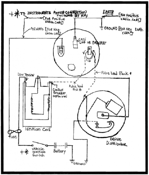
This (wiring) diagram was given to me by these helpful people as to wiring changes to make it work the way it is supposed to. Take the pulse lead from the #2 side of the ignition switch out of the block. Run this wire straight to the resistor block to start the engine. Run extra wiring for the pulse wire through the block to contact breaker terminal on the coil and to the distributor (as shown in the diagram1).
As my car is fitted with a 302 CI, Mallory dual point distributor, Mallory high performance coil and Ford LeMans cam CTFE-6250A, the top loop in the ignition pulse lead was removed (the wire runs straight through the block without the loop -see Fig. #2. Works excellent!
Although the Transistorized Assisted Ignition System directions are included I recommend that you would disregard same as they do not seem to work.
I hope these hints will help some members on their tach problem.
FITTING INSTRUCTIONS
Instrument Mounting
On many cars it will be possible to mount the tachometer in the fascia panel by cutting a suitable hole. The tachometer can then be retained in position with the fixing strap supplied. If there is insufficient room on the fascia panel, the fixing bracket supplied in the kit can be used to mount the instrument in a convenient position under the fascia panel. Always choose a mounting position which is free from excessive vibration.
Electrical Installation
Disconnect the battery feed lead and tie clear of battery.
Disconnect and discard the lead between the contact breaker terminal on the distributor and contact breaker terminal on the ignition coil.
Connecting Tachometer to Ignition Coil and Distributor
Connect the tachometer ignition pulse lead (the long white lead with Red and Black markers) as shown in the wiring diagram, i.e.,
* Negative Earth
Red marker to ignition coil and the Black marker to the distributor.
*Positive Earth
Black marker to ignition coil and the Red marker to the distributor.
*Important that these wires are hooked up correctly. (See diagram)
Pulse Lead Adjustment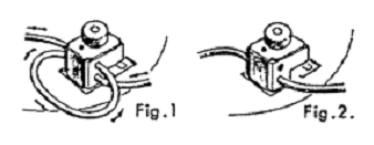
Adjustments to the length of each lead can be made by moving the lead through the block as shown in Fig. 1.
If the car is fitted with a high performance ignition coil it may be necessary to remove the top loop in the ignition pulse lead by sliding one end of the lead through the block as shown in Fig. 2.
Transistorized Assisted Ignition Systems (please see note by author above regarding the following:)
Providing the transistorized assisted ignition system is fitted with an ignition coil, the impulse tachometer will work satisfactorily.
It is necessary, however, to adopt the following general procedure when fitting the instrument in the vehicle:
a) The tachometer pulse lead should be connected in series with the ignition coil or ballast resistor the red marked lead being connected to the positive side of the ignition system and the black marked lead to the negative side.
b) One loop of the pulse lead should be removed from the plastic former as show in Fig. 2.
c) To obtain satisfactory operation over the complete dial range it may be necessary to reverse the pulse lead connections to that described in (a) above.