
by Tom Ehrhart in the November 1996 RootesReview
The mounting bracket is designed to take the badge bar and one or two lamp carriers. They are attached to the mounting bracket and then fitted to the car as an assembly, the driving lamps being added after assembly in order to avoid the possibility of damage during mounting.
![]()
LAMP CARRIER(S) – to fit
Using the bolts, nuts and washers provided, fit the lamp carrier(s) to the right or left hand side (or both) of the mounting bracket as shown.
BADGE BAR – to fit
Using the bolts, nuts and washers provided, fit the badge bar to the mounting bracket.
MOUNTING BRACKET – to fit
Remove the front bumper assembly and discard the bolts. Using the new bolts supplied in the kit and the original washers, refit the bumper assembly together with the mounting bracket. The mounting bracket is positioned between the bumper back bar and the chassis.
DRIVING LAMPS – to fit
Mount the lamp onto the carrier and route the cable via the grille and the under bonnet harness to the left-hand side of the facia on LHD vehicles (opposite on RHD) vehicles. Connect the earth wire (black) to one of the carrier bolts.
DRIVING LAMP SWITCH – to fit
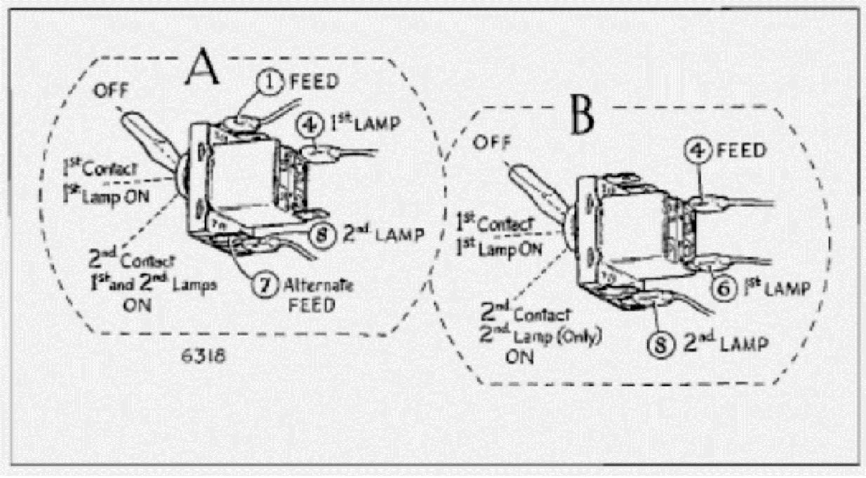
Drill a small hole in the blank recessed into the extreme left hand side of the facia on left hand vehicles (opposite for RHD). Using a rotary file, open out the hole to 9/16″ ( 14.5 mm) diameter. Fit the switch. Note: The switch is “off’ when the lever is towards terminal 1.
ELECTRICAL CONNECTIONS
It is left to the discretion of the owner as to how the switching of the auxiliary lamps is connected. Each method has advantages and disadvantages, therefore the only solution is the personal preference of the owner. This kit contains sufficient connectors to cater for the alternatives given below.
Disconnect the battery
If it is desired to have the auxiliary lamps operative only when the side lamps are switched on, proceeds as follows: Locate the red feed lead already provided in the main harness and connect to the switch as in “A” or “B.” Should the owner prefer the switch feed wired via the ignition switch, make up a lead using the “Lucar” connectors provided and connect it between the switch and terminal A4 of the fuse unit. Alternative connection for the lamps themselves are given under “A” and “B.”
A. Connect the cable from one lamp to terminal A4. Similarly connect the cable from the second lamp to terminal 8. Connect the red feed lead to terminal 1 of the switch. When connected in this manner, the switch will give one lamp on the first contact and both lamps on the second contact.
B. Alternatively, connect the cable from the first lamp to terminal 6 and the feed lead to terminal 4. The second lamp is connected to terminal 8 as in A on the previous page. This method of connection will give one lamp on the first contact and the other on the second contact.
Reconnect the battery, start clock (if fitted) and test lights.
![]()